21700 Power Tray

The Ashida will need to be powered from batteries and the build calls for 21700 Lithium Polymer batteries. I picked up a pair in the early phase of the build because the trimmed Wii, when hooked up to the RVL-PMS power management board must be powered by a LiPo battery. I’ve read that there are other options but these were cheap enough and required for the final build.

The 21700 is larger than a typical AA or 18650 LiPo which means the typical battery trays I have were not going to be useful.
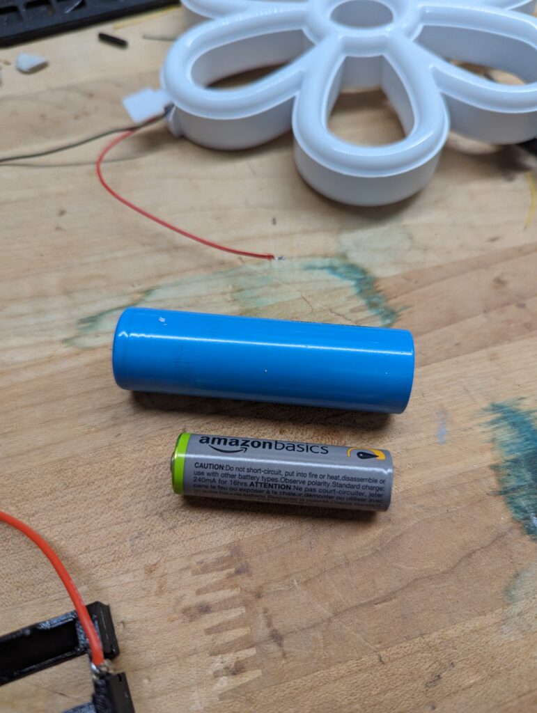
21700 vs AA for size comparison

I could purchase one that was the correct size but they’re $7-$10 before shipping and my budget for this month’s parts is all but spent.

Fortunately I was able to find a model on Thingiverse for a 21700 tray, but unfortunately, I didn’t have “battery clips.” These are the metal parts that make contact with the battery and allow you to connect it to things. Again, I could purchase these, and will need to for the final build, but I’m basically out of budget until next month.

So I dug around in my parts bin and found an LED light toy that the girls got as a present a while back. When we received it, for some reason, it came without a battery cover. This quickly became a problem as the batteries would fall out, or worse the girls would take them out to play with them. Eventually it ended up heading for the trash, but I diverted it to my parts bin. After all it had a switch and some LEDs, handy things that could be repurposed.

Well, tonight I cut into the battery compartment and ripped out the clips for the batteries. I cut them down to fit the tray I made, soldered on some wires, and I’ve got a working battery tray!
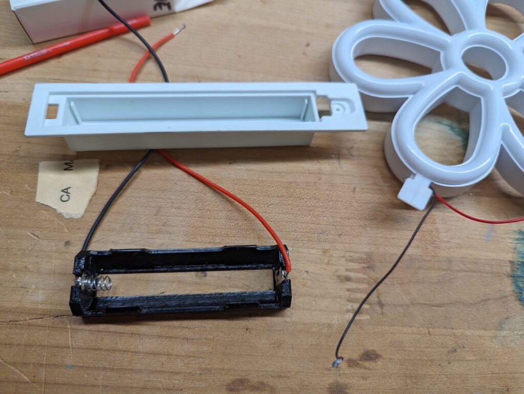
The tray I printed and the tray I scavenged parts from.
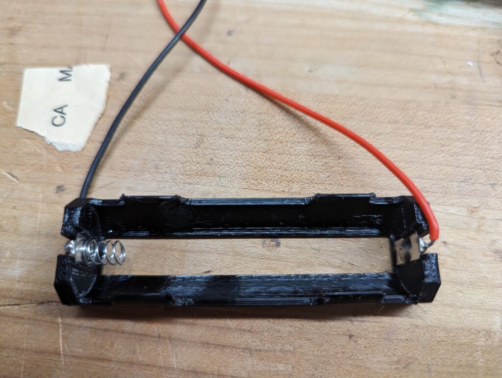
A close up of the tray with the clips installed and wires connected.

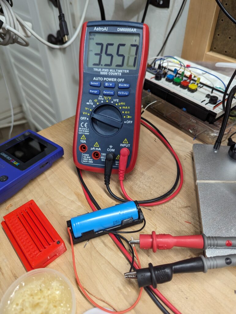
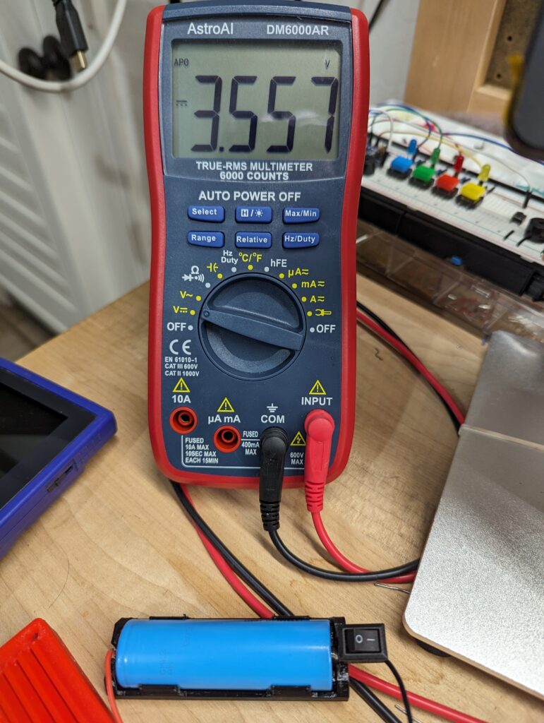
The tray, with battery, hooked up to the multimeter. Success!

For grins, I decided to wire on the switch that I scavenged as well. I figured this will give me a kill switch for the battery in case I ever need/want one. I could always pull the battery, but I’d rather reduce the strain on the clips which are just friction fit.
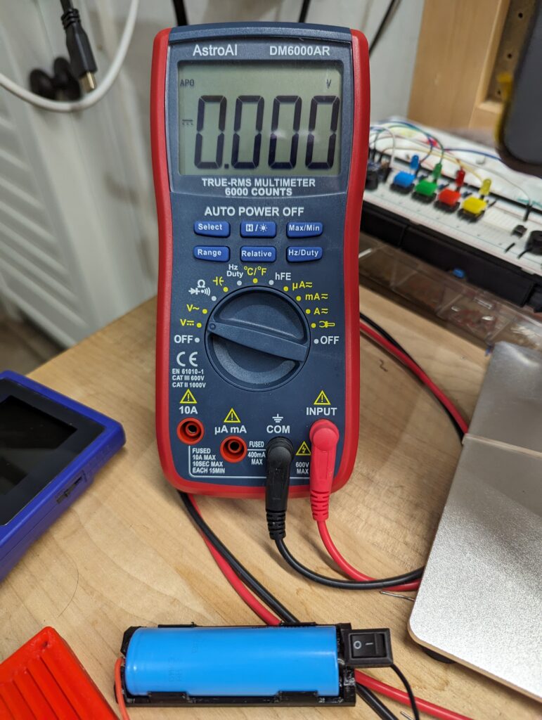
Switch is in the off position and voltage is 0.
Switch is in the on position and voltage is reading 3.5v

8-Bit Computer: Clock Circuit

This weekend I finished the Clock Circuit for the 8-bit computer that I’m building. The project uses prototyping boards (known as “breadboards”) instead of printed circuit boards and soldering. Breadboards are great because they make circuit building almost like Legos. You pop in wires and chips and can move them around and experiment without a lot of commitment.

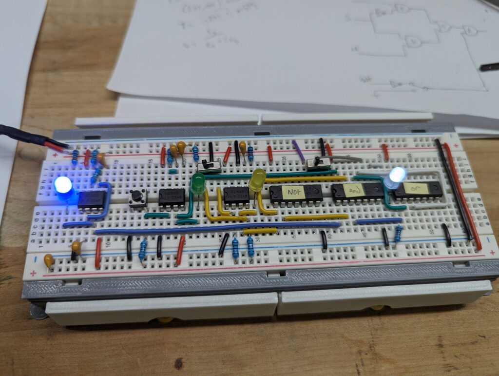
This Clock is the heartbeat of the coming computer. Each time it pulses the computer will advance one instruction. The pulsing is controlled with a “555 timer“, one of the most ubiquitous ICs (integrated circuits; a chip) in the world. Invented 51 years ago, it uses a clever bit of circuitry to create a stable and consistent pulse. Water is often an analogy for electricity, and it functions a bit like a cup, filling with water, then tipping over to empty, then righting itself and doing it all over. So long as the flow rate is constant, so too will be the timing of the fill and empty.

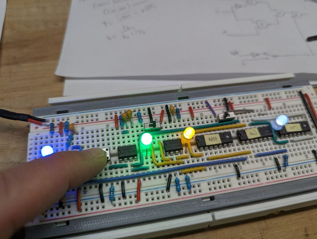
The build includes a way to manually pulse the clock and to control which pulse method is output, the auto pulse or manual.

I took some liberties with the source material. I chose to color code my wires to make clear which wires belong to which part of the Clock. This helped me a lot when working out the outputs on the right side of the circuit.

The original design uses a potentiometer to control the speed of the pulse in the automatic (Astable) circuit. I built mine using parts I had on hand and a few I picked up on Amazon with some gift certificates. Unfortunately, I had a potentiometer but it was about 1/10the the resistance that I needed to get it to work properly in this circuit. I ended up leaving it out, and will order a proper one when I buy the parts for the next part of the computer.

This project sources from Ben Eater’s work. I can’t say enough amazing things about Ben, his work, and his ability to explain the complex in incredibly simple terms. Einstein said, “If you can’t explain it simply, you don’t understand it well enough.” It’s clear Ben understands this. I would encourage anybody who wants to learn about and understand circuits to begin here. Especially if you want to know what the heck your computer is ACTUALLY doing.

Here’s a video of the full Clock Circuit in action.

FireTV Photo Frame

I’ve long been in search of the holy grail of family photos: My TVs showing my family pictures at all times. I sync all my photos to Google Photos for backup and this makes my Google Chromecasts happy. They can default to my photo collection and they do a great job of choosing interesting pics and displaying them in clever ways.

Unfortunately though, all my TVs actually use Amazon Fire TVs. So a few years ago I started syncing my photos to Amazon as well and I set my screensaver to show my family photos. This is a good solution, but the FireTVs shut themselves off after 20 minutes of inactivity and you can’t set the screensaver timeout for less than 5 minutes. So that gives you 15 minutes of photos as your best bet, with 5 minutes of useless advertisements on the homescreen.

Fortunately there’s a solution to this problem. AFTV News details how to set the screensaver and time off timeout using adb but I wanted to take that just one step further. I wrote a really simple shell script that you can run on the firetv to set the screensaver start time and the firetv shut down time.

Here’s the script:

# Use this to set the screensaver on a firetv
# you can't set it as executable (unless you're rooted)
# so you need to run it as:
# $ source ./sleep_settings.sh
echo "Enter screensaver timeout in minutes (Default 5)"
read SCREENSAVER_ON_IN_MINUTES
echo "Enter screen off timeout in minutes (Default 20)"
read SLEEP_IN_MINUTES

SCREENSAVER_IN_MILLISECONDS=`expr "$SCREENSAVER_ON_IN_MINUTES" \* 60000`
SLEEP_IN_MILLISECONDS=`expr "$SLEEP_IN_MINUTES" \* 60000`

set -x
settings put system screen_off_timeout $SCREENSAVER_IN_MILLISECONDS
settings put secure sleep_timeout $SLEEP_IN_MILLISECONDS
set +x

Save the script to a file, I’ll assume you name it sleep_settings.sh. Once you’ve done that run the following:

adb kill-server
adb connect <IP Of Your FireTV>
adb push sleep_settings.sh /sdcard
adb shell
source /sdcard/sleep_settings.sh
exit

That’s it! I set the screen saver to 1 minute and the sleep timeout to 120 minutes. This kicks on my photos quickly and lets them run for a while.